Three-Phase OLTC Regulating Transformer (Phasor Type)
Implement phasor model of three-phase OLTC regulating transformer
Library
Simscape / Electrical / Specialized Power Systems / Power Grid Elements
Description
This block is used to model a three-phase two-winding transformer or autotransformer using an on-load tap changer (OLTC) for regulating voltage on a transmission or distribution system. Controlling voltage on a transmission system affects primarily flow of reactive power, which, in turn, affects the power transfer limits. Although the regulating transformer does not provide as much flexibility and speed as power-electronics based FACTS, it can be considered as a basic power flow controller. This is why it has been included in the facts library. The dynamic performance of the regulating transformer can be enhanced by using a thyristor-based tap changer instead of a mechanical tap changer. As this model is a phasor model which does not implement the details of current commutation from one tap to the next tap, you can use it to model a thyristor-based tap changer and implement your own control system by selecting External control of OLTC in the block menu. You can also use this block together with the Three-phase OLTC Phase-Shifting Transformer Delta-Hexagonal (Phasor Type) block for building phasor models of more complex transformer-based FACTS topologies.
The figure below shows one phase of the three-phase regulating transformer. Each phase consists of main windings 1 and 2 and of a tapped regulation winding.
One Phase of the Regulating Transformer
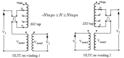
–Ntaps ≤ N ≤ +Ntaps. The voltage ratios on the two windings are:
| Winding 1 | Winding 2 |
|---|---|
Voltage regulation is performed by varying the transformer ratio V2/V1 by means of the OLTC. The OLTC can be connected either on winding 1 (left diagram) or on winding 2 (right diagram). The OLTC can select any tap from position 0 (no voltage correction) to maximum tap (position Ntap) yielding maximum voltage correction. The OLTC is also equipped with a reversing switch which allows connecting the regulation winding either in additive or subtractive polarity. The factor multiplying Vnom2/Vnom1 is the voltage correction factor. It is given by:
1/(1 + N ΔU) for OLTC on winding
1
1 + N ΔU for OLTC on winding
2
where
N = tap position
ΔU = voltage
per tap in pu of nominal voltage of winding 1 or winding 2.
Negative values of N correspond to the reversing switch position shown in dashed lines (regulation winding in subtractive polarity). The transformer resistance and leakage reactance also vary with the tap position.
Mechanical tap changers are relatively slow devices. The time required to move from one tap position to the next one is comprised between 3 and 10 seconds. You specify this mechanical time delay in the block menu.
Note
OLTCs use additional switches and resistors (or inductors) to transfer current from the
outgoing tap to the ongoing tap without interrupting load current. During the transfer, taps
are temporarily short circuited through resistors or inductors. The transfer time (typically
from 40 ms to 60 ms) is fast as compared to the tap selection process (3 s to 10 s). As this
block implements a phasor model for study of transient stability of power systems in the range
of seconds to minutes, the tap transfer process is not modelled and an instantaneous tap
transfer is assumed. A detailed regulating transformer model is provided in the
power_OLTCregtransformer example.
Automatic Voltage Control
The regulating transformer is associated with a control system which regulates voltage at the transformer terminals (side 1 or side 2) or at a remote bus. Such a control system is provided in the Three-Phase OLTC Regulating Transformer (Phasor Type) block. You then connect at the Vm input of the block a Simulink® signal, which is usually the magnitude of the positive-sequence voltage (in pu) to be controlled, but it can be any signal.The control system adjusts automatically the tap position until the measured voltage Vm is equal to the reference voltage Vref specified in the block menu.
The voltage regulator is a hysteresis type regulator. Each time a tap change is required, the regulator sends a pulse either to the Up or Down input of the Tap Changer Controller. Look under the block mask to see how these control blocks are built. The regulator asks for a tap change if
|Vm – Vref| > DeadBand/2
during a time t >Delay, where Vref, DeadBand, and Delay are parameters of the voltage regulator.
External Control of OLTC
If you want to implement your own control system or manually control the tap position, you select External control of OLTC. The Vm input is then replaced by two inputs labeled Up and Down. Applying a pulse to the Up or Down input moves the tap position upward or downward when the signal is changing from 0 to 1.
Parameters
The transformer and OLTC parameters are grouped in two categories: Transformer
parameters and OLTC and Voltage Regulator parameters. Use the
Show listbox to select which group of parameters you want to
visualize.
Transformer Tab
- Winding 1 connection (ABC terminals)
The connection of the three windings 1. Select
Y(ungrounded wye),Yg(wye grounded),Delta(D1)(Delta connection introducing a −30 degrees phase-shift) orDelta(D11)(Delta connection introducing a +30 degrees phase-shift). Default isY. For an explanation of the phase shifts introduced by D1and D11 connections, see the Three-Phase Transformer (Two-Windings) block documentation. The zero-sequence impedance will vary according to the connection. Zero-sequence impedance is computed assuming that the three-phase transformer bank is built with three single-phase, two-winding units.- Winding 2 connection (abc terminals)
The connection of the three windings 2. Select
Y(ungrounded wye),Yg(wye grounded),Delta(D1)(Delta connection introducing a −30 degrees phase-shift) orDelta(D11)(Delta connection introducing a +30 degrees phase-shift). Default isDelta(D1). The zero-sequence impedance will vary according to the connection.- Nominal Power and frequency
The three-phase nominal power, in VA and the nominal frequency, in hertz. Default is
[47e6, 60].- Winding 1 parameters
The nominal line to line voltage of winding 1, in volts rms, winding resistance, in pu, and leakage reactance, in pu. Default is
[120e3, 0.003, 0.09 ].- Winding 2 parameters
The nominal line to line voltage of winding 2, in volts rms, winding resistance in pu, and leakage reactance, in pu. Default is
[25e3, 0.003, 0.09 ].- Initial pos. seq. output currents of winding 2
The initial value of the positive-sequence current phasor (Magnitude in pu and Phase in degrees) flowing out of winding 2. The currents flowing into winding 1 will be computed accordingly. If you know the initial value of currents you may specify it in order to start simulation in steady state. If you don't know these values, you can leave [0 0]. The system will reach steady-state after a short transient. Default is
[0.7568, -45].- Magnetizing branch
The resistance, in pu and the reactance, in pu, of the parallel Rm, Xm branch modelling respectively iron losses and reactive magnetizing currents. Saturation is not modelled. Default is
[300, 300].
OLTC and Voltage Regulator Tab
- OLTC on
Select either
Winding 1(default) orWinding 2.- Tapped regulation winding
The resistance and the leakage reactance of the tapped winding depend on the tap position. Enter the resistance, in pu, and the leakage reactance, in pu, corresponding to the maximum tap position. Default is
[ 0.003, 0.09].- Voltage step per tap
The voltage step per tap, in pu of the nominal voltage of winding 1 or winding 2. Default is
0.01875.- Minimum and maximum tap positions
You normally specify a negative integer corresponding to maximum tap position with the regulation winding connected in subtractive polarity, followed by a positive integer corresponding to maximum tap position with the regulation winding connected in additive polarity. These two integers specify the number of taps and their absolute values are usually the same. However, if you want to limit tap excursion, you may specify two different values. Default is
[ -8, +8].- Initial tap position
Specify an integer N corresponding to initial tap position with MinTap≤ N ≤MaxTap. Default is
-4.- Tap selection time
The mechanical time delay, in seconds, required for the OLTC to move the taps by one position. Typical values are in the 3s-10s range. Default is
4.- External control of OLTC
The OLTC is usually controlled by the voltage regulator. Select this parameter if you want to implement your own control system or manually control the tap position. The Vm input will then be replaced by two inputs labeled Up and Down. Applying a pulse to the Up or Down input will move the tap position upward or downward when the signal is changing from 0 to 1. Default is cleared.
- Voltage regulator
This parameter is not visible when the External control of OLTC parameter is selected.
Select
on(default) for enabling the voltage regulator. If you selectoffthe OLTC is frozen at the position specified by the Initial tap position parameter.- Regulator parameters
This parameter is not visible when the External control of OLTC parameter is checked.
Specify the reference voltage Vref, in pu, the dead band of the hysteresis regulator, in pu, and the time delay, in seconds, during which the voltage error must exceed half the dead band for the OLTC to move tap position upward or downward. The dead band is normally adjusted at two times the voltage step specified in the Voltage step per tap parameter. Default is
[1.04, 0.0375, 1].
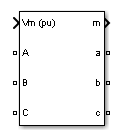
Inputs and Outputs
A B CThe three input terminals connected windings 1.
a b cThe three output terminals connected to windings 2.
VmThis input is visible only when the External control of OLTC parameter is not checked.
Connect to this input the measured voltage to be controlled by the voltage regulator. This signal is usually the magnitude, in pu, of the positive-sequence voltage measured at the transformer terminals (side 1 or side 2) or at a remote bus.
UpThis input is visible only when the External control of OLTC parameter is checked.
Simulink input for controlling tap position. Applying a pulse to this input will initiate upward tap changing when the pulse is changing from 0 to 1.
DownThis input is visible only when the External control of OLTC parameter is checked.
Simulink input for controlling tap position. Applying a pulse to this input will initiate downward tap changing when the pulse is changing from 0 to 1.
mSimulink output vector containing 16 internal signals. These signals are either complex signals (voltage phasors, current phasors or impedances) or control signals. They can be individually accessed by using the Bus Selector block. They are, in order:
Signal
Signal Group
Signal Names
Definition
1-3
VABC (cmplx)
VA (pu)
VB (pu)
VC (pu)Phasor voltages (phase to ground) at the transformer input terminals A, B, C (pu)
4-6
Vabc (cmplx)
Va (pu)
Vb (pu)
Vc (pu)Phasor voltages (phase to ground) at the transformer output terminals a, b, c (pu)
7-9
IABC (cmplx)
IA (pu)
IB (pu)
IC (pu)Phasor currents flowing into the input terminals A, B, C
10-12
Iabc (cmplx)
Ia (pu)
Ib (pu)
Ic (pu)Phasor currents flowing out of the output terminals a, b, c
13-14
Z (cmplx)
Z1 (pu)
Z0 (pu)Positive- and zero-sequence complex impedances (R+jX)
15
Tap
Tap
Tap position
16
Ready
Ready
Logical signal generated by the tap changer controller. This signal is used to enable voltage controller action. The Ready signal becomes (1) after the tap selection has been completed, thus enabling a new tap change. The Up and Down pulses to the OLTC are blocked as long as the Ready signal is (0).
Examples
See the power_OLTCregtransformer example, which illustrates the use of
the Three-Phase OLTC Regulator Transformer (Phasor Type) block to regulate voltage on a 25-kV
distribution feeder. The phasor model is compared with a detailed model of regulating
transformer. Look under the masked blocks to see how both models are implemented. The detailed
model uses switches and three Multi-Winding Transformer blocks, whereas the phasor model uses
current sources.
Version History
Introduced in R2006a
You can also select a web site from the following list:
Americas
- América Latina (Español)
- Canada (English)
- United States (English)
Europe
- Belgium (English)
- Denmark (English)
- Deutschland (Deutsch)
- España (Español)
- Finland (English)
- France (Français)
- Ireland (English)
- Italia (Italiano)
- Luxembourg (English)
- Netherlands (English)
- Norway (English)
- Österreich (Deutsch)
- Portugal (English)
- Sweden (English)
- Switzerland
- United Kingdom (English)