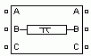
Three-Phase PI Section Line
Implement three-phase transmission line section with lumped parameters
Libraries:
Simscape /
Electrical /
Specialized Power Systems /
Power Grid Elements
Description
The Three-Phase PI Section Line block implements a balanced three-phase transmission line model with parameters lumped in a PI section.
Contrary to the Distributed Parameters Line model where the resistance, inductance, and capacitance are uniformly distributed along the line, the Three-Phase PI Section Line block lumps the line parameters in a single PI section as shown in the figure below.
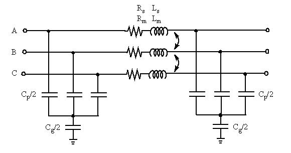
The line parameters R, L, and C are specified as positive- and zero-sequence parameters that take into account the inductive and capacitive couplings between the three phase conductors, as well as the ground parameters. This method of specifying line parameters assumes that the three phases are balanced.
The self and mutual resistances (Rs, Rm), self and mutual inductances (Ls, Lm) of the three coupled inductors, as well as phase capacitances Cp and ground capacitances Cg, are deduced from the positive- and zero-sequence RLC parameters as follows.
Let us assume the following line parameters:
| r1, r0 | Positive- and zero-sequence resistances per unit length (Ω/km) |
| l1, l0 | Positive- and zero-sequence inductances per unit length (H/km) |
| c1, c0 | Positive- and zero-sequence capacitances per unit length (F/km) |
| f | Frequency (Hz) |
| lsec | Line section length (km) |
The total positive- and zero-sequence RLC parameters including hyperbolic corrections are first evaluated:
where
kr1, kl1, kc1, kr0, kl0, kc0 — positive-sequence and zero-sequence hyperbolic correction factors
Note
See the PI Section Line block reference page for an explanation on how to compute RLC parameters taking into account hyperbolic corrections.
The Powergui block provides a graphical tool for the calculation of
resistance, inductance, and capacitance per unit length based on the line geometry and the
conductor characteristics. See the power_lineparam reference page to learn how to use this tool.
For a short line section (approximately lsec < 50 km), these correction factors are negligible (close to unity). However, for long lines, these hyperbolic corrections must be taken into account in order to get an exact line model at the specified frequency.
The RLC line section parameters are then computed as follows:
Examples
The power_triphaseline example illustrates voltage transients at the
receiving end of a 200-km line when only phase A is energized. Voltages obtained with two
line models are compared: 1) the Distributed Parameters Line block and 2) a PI line model
using two Three-Phase PI Section Line blocks.
Ports
Conserving
Parameters
Extended Capabilities
Version History
Introduced before R2006a
See Also
You can also select a web site from the following list:
Americas
- América Latina (Español)
- Canada (English)
- United States (English)
Europe
- Belgium (English)
- Denmark (English)
- Deutschland (Deutsch)
- España (Español)
- Finland (English)
- France (Français)
- Ireland (English)
- Italia (Italiano)
- Luxembourg (English)
- Netherlands (English)
- Norway (English)
- Österreich (Deutsch)
- Portugal (English)
- Sweden (English)
- Switzerland
- United Kingdom (English)