Main Content

Battery

Behavioral battery model

  • Battery block

Libraries:
Simscape / Electrical / Sources
Simscape / Battery / Cells

Description

The Battery block represents a simple battery model. You can also expose the charge output port and the thermal port of the battery.

To measure the internal charge level of the battery, in the Main section, set the Expose charge measurement port to Yes. This action exposes an extra physical signal port that outputs the internal state of charge. Use this functionality to change load behavior as a function of state of charge, without the complexity of building a charge state estimator.

To simulate the thermal effects of the battery, in the Thermal Port section, set the Thermal port parameter to Model. This action exposes an extra thermal port, which represents the battery thermal mass. When you select this option, provide additional parameters to define battery behavior at a second temperature. For more information, see Modeling Thermal Effects.

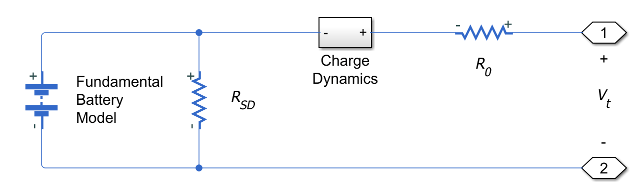
The battery equivalent circuit is made up of the fundamental battery model, the self-discharge resistance RSD, the charge dynamics model, and the series resistance R0.

Battery Model

If you select Infinite for the Battery charge capacity parameter, the block models the battery as a series resistor and a constant voltage source. If you select Finite for the Battery charge capacity parameter, the block models the battery as a series resistor and a charge-dependent voltage source. In the finite case, the voltage is a function of charge and has the following relationship:

V=V0(SOC1β(1SOC))

where:

  • SOC (state-of-charge) is the ratio of current charge to rated battery capacity.

  • V0 is the voltage when the battery is fully charged at no load, as defined by the Nominal voltage, Vnom parameter.

  • β is a constant that is calculated so that the battery voltage is V1 when the charge is AH1. Specify the voltage V1 and cell capacityAH1 using block parameters. AH1 is the charge when the no-load (open-circuit) voltage is V1, and V1 is less than the nominal voltage.

The equation defines an approximate relationship between voltage and remaining charge. This approximation replicates the increasing rate of voltage drop at low charge values, and ensures that the battery voltage becomes zero when the charge level is zero. The advantage of this model is that it requires few parameters, which are readily available on most datasheets.

Modeling Battery Fade

For battery models with finite battery charge capacity, you can model battery performance deterioration depending on the number of discharge cycles. This deterioration is referred to as battery fade. To enable battery fade, set the Battery fade parameter to Enabled. This setting exposes additional parameters in the Fade section.

The block implements battery fade by scaling certain battery parameter values that you specify in the Main section, depending on the number of completed discharge cycles. The block uses multipliers λAH, λR0, and λV1 on the Cell capacity (Ah rating), Internal resistance, and Voltage V1 when charge is AH1 parameter values, respectively. These multipliers, in turn, depend on the number of discharge cycles:

λAH=1k1N0.5

λR0=1+k2N0.5

λV1=1k3N

N=N0+1AH0ti(t)H(i(t))λAH(t)dt

where:

  • λAH is the multiplier for battery nominal capacity.

  • λR0 is the multiplier for battery series resistance.

  • λV1 is the multiplier for voltage V1.

  • N is the number of discharge cycles completed.

  • N0 is the number of full discharge cycles completed before the start of the simulation.

  • AH is the rated battery capacity in ampere-hours.

  • i(t) is the instantaneous battery output current.

  • H(i(t)) is the Heaviside function of the instantaneous battery output current. This function returns 0 if the argument is negative, and 1 if the argument is positive.

The block calculates the coefficients k1, k2, and k3 by substituting the parameter values you provide in the Fade section into these battery equations. For example, the default set of block parameters corresponds to the following coefficient values:

  • k1 = 1e-2

  • k2 = 1e-3

  • k3 = 1e-3

You can also define a starting point for a simulation based on the previous charge-discharge history by using the high-priority variable Discharge cycles. For more information, see Variables.

Modeling Thermal Effects

If you set the Thermal port parameter to Model, you must provide additional parameters to define battery behavior at a second temperature. The extended equations for the voltage when you expose the thermal port are:

V=V0T(SOC1βT(1SOC))

V0T=V0(1+λV(TT1))

where:

  • T is the battery temperature.

  • T1 is the nominal measurement temperature.

  • λV is the parameter temperature dependence coefficient for V0.

  • βT=β[1+λβ(TT1)].

  • λβ is the parameter temperature dependence coefficient for β.

  • β is calculated in the same way as Battery Model, using the temperature-modified nominal voltage V0T.

The internal series resistance, self-discharge resistance, and any charge-dynamic resistances are also functions of temperature:

RT=R(1+λR(TT1))

where λR is the parameter temperature dependence coefficient.

All the temperature dependence coefficients are determined from the corresponding values you provide at the nominal and second measurement temperatures. If you include charge dynamics in the model, the time constants vary with temperature in the same way.

The battery temperature is determined from a summation of all the ohmic losses included in the model:

MthT˙=iVT,i2/RT,i

where:

  • Mth is the battery thermal mass.

  • i corresponds to the ith ohmic loss contributor. Depending on how you have configured the block, the losses include:

    • Series resistance

    • Self-discharge resistance

    • First charge dynamics segment

    • Second charge dynamics segment

    • Third charge dynamics segment

    • Fourth charge dynamics segment

    • Fifth charge dynamics segment

  • VT,i is the voltage drop across resistor i.

  • RT,i is resistor i.

Modeling Charge Dynamics

You can model battery charge dynamics by using the Charge dynamics parameter:

  • No dynamics — The equivalent circuit contains no parallel RC sections. There is no delay between terminal voltage and internal charging voltage of the battery.

  • One time-constant dynamics — The equivalent circuit contains one parallel RC section. Specify the time constant using the First time constant parameter.

  • Two time-constant dynamics — The equivalent circuit contains two parallel RC sections. Specify the time constants using the First time constant and Second time constant parameters.

  • Three time-constant dynamics — The equivalent circuit contains three parallel RC sections. Specify the time constants using the First time constant, Second time constant, and Third time constant parameters.

  • Four time-constant dynamics — The equivalent circuit contains four parallel RC sections. Specify the time constants using the First time constant, Second time constant, Third time constant, and Fourth time constant parameters.

  • Five time-constant dynamics — The equivalent circuit contains five parallel RC sections. Specify the time constants using the First time constant, Second time constant, Third time constant, Fourth time constant, and Fifth time constant parameters.

This figure shows the equivalent circuit for the block configured with two time-constant dynamics.
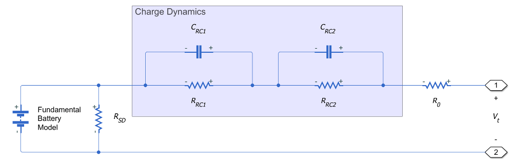
In the diagram:

  • RRC1 and RRC2 are the parallel RC resistances. Specify these values with the First polarization resistance and Second polarization resistance parameters, respectively.

  • CRC1 and CRC2 are the parallel RC capacitances. The time constant τ for each parallel section relates the R and C values using the relationship C=τ/R. Specify τ for each section using the First time constant and Second time constant parameters, respectively.

  • R0 is the series resistance. Specify this value with the Internal resistance parameter.

Modeling Battery Aging

For battery models with finite battery charge capacity, you can model the battery performance deterioration that occurs when the battery is not used. Calendar aging affects both the internal resistance and capacity. In particular, the resistance increase depends by various mechanisms such as the creation of Solid Electrolyte Interface (SEI) at both anode and cathode and the corrosion of the current collector. These processes mainly depends on the storage temperature, the storage state of charge, and time.

Note

The Battery block only applies the calendar aging during initialization. When you set the Calendar aging parameter to Enabled, the block exposes the Vector of time intervals parameter that represents the time the battery has aged before the start of the simulation. Calendar aging during the simulation is not covered with this option.

This equation defines the terminal resistance increase of the battery due to calendar aging:

αr(T,Voc)=(bVocc)eqdkT,R=R0(1+i=1i=nαr(Ti,Voc)(tiati1a)),

where:

  • Voc is the Normalized open-circuit voltage during storage, V/Vnom.

  • R0 is the Internal resistance.

  • ti is the time sample derived from the Vector of time intervals parameter.

  • Ti is derived from the Vector of temperatures parameter.

  • b is the Linear scaling for voltage, b.

  • c is the Constant offset for voltage, c.

  • d is the Temperature-dependent exponential increase, d.

  • a is the Time exponent, a.

  • q is the electron's elementary charge, in C.

  • k is the Boltzmann constant, in J/K.

The R1_age_multiplier variable in the Simscape Results Explorer stores the calendar aging of the battery in terms of resistance increase:

R1_age_multiplier=RR0.

For thermal modeling options of the block, if you set the Storage condition parameter to Fixed open-circuit voltage, you must specify the additional Open-circuit voltage measurement temperature parameter to convert the storage open-circuit voltage to the temperature-independent state of charge during storage:

SOC=OCV(1β(TOCVmeasurement))1β(TOCVmeasurement)OCV.

The open-circuit voltage according to the storage temperature is then defined by this equation:

OCVTstorage=SOC1β(Tstorage)(1β(Tstorage)SOC).

Finally, this equation defines the terminal resistance increase of the battery due to calendar aging according to the storage temperature:

R=R0(1+i=1i=nαr(Tstoragei,OCVTstoragei)(tiati1a)).

Plotting Voltage-Charge Characteristics

A quick plot feature lets you visualize the voltage-charge characteristic for the battery model parameter values. To plot the characteristics, right-click a Battery block in your model and, from the context menu, select Electrical > Basic characteristic. The software automatically computes a set of bias conditions, based on the block parameter values, and opens a figure window containing a plot of no-load voltage versus the state-of-charge (SOC) for the block. For more information, see Plot Basic Characteristics for Battery Blocks.

Variables

To set the priority and initial target values for the block variables before simulation, use the Initial Targets section in the block dialog box or Property Inspector. For more information, see Set Priority and Initial Target for Block Variables.

Use nominal values to specify the expected magnitude of a variable in a model. Using system scaling based on nominal values increases the simulation robustness. Nominal values can come from different sources. One of these sources is the Nominal Values section in the block dialog box or Property Inspector. For more information, see System Scaling by Nominal Values.

When you model battery fade, the Discharge cycles variable lets you specify the number of charge-discharge cycles completed prior to the start of simulation. If you disable battery fade modeling, this variable is not used by the block.

Assumptions and Limitations

  • The self-discharge resistance is assumed not to depend strongly on the number of discharge cycles.

  • For the thermal modeling option of the battery, you provide fade data only for the reference temperature operation. The block applies the same derived λAH, λR0, and λV1 multipliers to parameter values corresponding to the second temperature.

  • When using the thermal block modeling options, use caution when operating at temperatures outside of the temperature range bounded by the Measurement temperature and Second measurement temperature values. The block uses linear interpolation for the derived equation coefficients, and simulation results can become nonphysical outside of the specified range. The block checks that the internal series resistance, self-discharge resistance, and nominal voltage always remain positive. If there is a violation, the block issues error messages.

Ports

Output

expand all

Physical signal port that outputs the internal charge, in the units of coulomb (C). Use this output port to change load behavior as a function of charge, without the complexity of building a charge state estimator.

Dependencies

To enable this port, set Expose charge measurement port to Yes.

Conserving

expand all

Electrical conserving port associated with the battery positive terminal.

Electrical conserving port associated with the battery negative terminal.

Thermal conserving port that represents the battery thermal mass. When you expose this port, provide additional parameters to define battery behavior at a second temperature. For more information, see Modeling Thermal Effects.

Dependencies

To enable this port, in the Thermal Port section, set Thermal port to Model.

Parameters

expand all

Main

No-load voltage across the battery when it is fully charged.

Whether to enable current directionality. If you set this parameter to Enabled, the terminal resistance depends on the direction of the current.

Internal connection resistance of the battery.

Dependencies

To enable this parameter, set Current directionality to Disabled.

Internal connection resistance of the battery during charge phase.

Dependencies

To enable this parameter, set Current directionality to Enabled.

Internal connection resistance of the battery during discharge phase.

Dependencies

To enable this parameter, set Current directionality to Enabled.

Select one of the options for modeling the charge capacity of the battery:

  • Infinite — The battery voltage is independent of charge drawn from the battery.

  • Finite — The battery voltage decreases as charge decreases.

Maximum (nominal) battery charge in ampere-hours. To specify a target value for the initial battery charge at the start of simulation, use the high-priority Charge variable. For more information, see Variables.

Dependencies

To enable this parameter, set Battery charge capacity to Finite.

Fundamental battery output voltage when the charge level is AH1, as specified by the Charge AH1 when no-load voltage is V1 parameter. This parameter must be less than Nominal voltage, Vnom.

Dependencies

To enable this parameter, set Battery charge capacity to Finite.

Battery charge level corresponding to the no-load output voltage specified by the Voltage V1 when charge is AH1 parameter.

Dependencies

To enable this parameter, set Battery charge capacity to Finite.

Select whether to model the self-discharge resistance of the battery. The block models this effect as a resistor across the terminals of the fundamental battery model.

As temperature increases, self-discharge resistance decreases, causing self-discharge to increase. If the decrease in resistance is too fast, thermal runaway of the battery and numerical instability can occur. You can resolve this by doing any of the following:

  • Decrease the thermal resistance

  • Decrease the gradient of the self-discharge resistance with respect to temperature

  • Increase the self-discharge resistance

Dependencies

To enable this parameter, set Battery charge capacity to Finite.

Resistance across the fundamental battery model that represents battery self-discharge.

Dependencies

To enable this parameter, set Self-discharge to Enabled.

Temperature T1, at which the block parameters in the Main section are measured. For more information, see Modeling Thermal Effects.

Dependencies

To enable this parameter, in the Thermal Port section, set Thermal port to Model.

Since R2023a

Whether to expose the charge measurement port and measure the internal charge level of the battery.

Dynamics

Select how to model battery charge dynamics. This parameter determines the number of parallel RC sections in the equivalent circuit:

  • No dynamics — The equivalent circuit contains no parallel RC sections. There is no delay between terminal voltage and internal charging voltage of the battery.

  • One time-constant dynamics — The equivalent circuit contains one parallel RC section. Specify the time constant using the First time constant parameter.

  • Two time-constant dynamics — The equivalent circuit contains two parallel RC sections. Specify the time constants using the First time constant and Second time constant parameters.

  • Three time-constant dynamics — The equivalent circuit contains three parallel RC sections. Specify the time constants using the First time constant, Second time constant, and Third time constant parameters.

  • Four time-constant dynamics — The equivalent circuit contains four parallel RC sections. Specify the time constants using the First time constant, Second time constant, Third time constant, and Fourth time constant parameters.

  • Five time-constant dynamics — The equivalent circuit contains five parallel RC sections. Specify the time constants using the First time constant, Second time constant, Third time constant, Fourth time constant, and Fifth time constant parameters.

Resistance of the first parallel RC section. This parameter primarily affects the ohmic losses of the RC section.

Dependencies

To enable this parameter, set Charge dynamics to One time-constant dynamics, Two time-constant dynamics, Three time-constant dynamics, Four time-constant dynamics, or Five time-constant dynamics.

Time constant of the first parallel RC section. This value is equal to RC and affects the dynamics of the RC section.

Dependencies

To enable this parameter, set Charge dynamics to One time-constant dynamics, Two time-constant dynamics, Three time-constant dynamics, Four time-constant dynamics, or Five time-constant dynamics.

Resistance of the second parallel RC section. This parameter primarily affects the ohmic losses of the RC section.

Dependencies

To enable this parameter, set Charge dynamics to Two time-constant dynamics, Three time-constant dynamics, Four time-constant dynamics, or Five time-constant dynamics.

Time constant of the second parallel RC section. This value is equal to RC and affects the dynamics of the RC section.

Dependencies

To enable this parameter, set Charge dynamics to Two time-constant dynamics, Three time-constant dynamics, Four time-constant dynamics, or Five time-constant dynamics.

Resistance of the third parallel RC section. This parameter primarily affects the ohmic losses of the RC section.

Dependencies

To enable this parameter, set Charge dynamics to Three time-constant dynamics, Four time-constant dynamics, or Five time-constant dynamics.

Time constant of the third parallel RC section. This value is equal to RC and affects the dynamics of the RC section.

Dependencies

To enable this parameter, set Charge dynamics to Three time-constant dynamics, Four time-constant dynamics, or Five time-constant dynamics.

Resistance of the fourth parallel RC section. This parameter primarily affects the ohmic losses of the RC section.

Dependencies

To enable this parameter, set Charge dynamics to Four time-constant dynamics or Five time-constant dynamics.

Time constant of the fourth parallel RC section. This value is equal to RC and affects the dynamics of the RC section.

Dependencies

To enable this parameter, set Charge dynamics to Four time-constant dynamics or Five time-constant dynamics.

Resistance of the fifth parallel RC section. This parameter primarily affects the ohmic losses of the RC section.

Dependencies

To enable this parameter, set Charge dynamics to Five time-constant dynamics.

Time constant of the fifth parallel RC section. This value is equal to RC and affects the dynamics of the RC section.

Dependencies

To enable this parameter, set Charge dynamics to Five time-constant dynamics.

Fade

Select whether to include battery fade modeling:

  • Disabled — The battery performance is not age dependent.

  • Enabled — The battery performance changes depending on the number of completed charge-discharge cycles. Selecting this option exposes additional parameters in this section, which define the battery performance after a certain number of discharge cycles. The block uses these parameter values to calculate the scaling coefficients k1, k2, and k3. For more information, see Modeling Battery Fade.

Dependencies

To enable this parameter, in the Main section, set Battery charge capacity to Finite. If Battery charge capacity is Infinite, the Fade section is empty.

Number of charge-discharge cycles after which the other parameters in this section are measured. This second set of data points defines the scaling coefficients k1, k2, and k3, used in modeling battery fade.

Dependencies

To enable this parameter, set Battery fade to Enabled.

Maximum battery charge, in ampere-hours, after the number of discharge cycles specified by the Number of discharge cycles, N parameter.

Dependencies

To enable this parameter, set Battery fade to Enabled.

Battery internal resistance after the number of discharge cycles specified by the Number of discharge cycles, N parameter.

Dependencies

To enable this parameter, set Battery fade to Enabled and, in the Main section, set Current Directionality to Disabled.

Average of the battery charge and discharge internal resistance after the number of discharge cycles specified by the Number of discharge cycles, N parameter.

Dependencies

To enable this parameter, set Battery fade to Enabled and, in the Main section, set Current Directionality to Enabled.

Fundamental battery model output voltage, at charge level AH1, after the number of discharge cycles specified by the Number of discharge cycles, N parameter.

Dependencies

To enable this parameter, set Battery fade to Enabled.

Calendar Aging

To expose these parameters, in the Main tab, set Battery charge capacity to Finite.

Whether to enable calendar aging of the battery.

Whether to specify the open-circuit voltage or the state of charge during storage.

Dependencies

To enable this parameter, set Calendar aging to Enabled.

Normalized open-circuit voltage during storage.

Dependencies

To enable this parameter, set Calendar aging to Enabled and Storage condition to Fixed open-circuit voltage.

Open-circuit measurement temperature.

Dependencies

To enable this parameter, expose the block thermal port and set Calendar aging to Enabled and Storage condition to Fixed open-circuit voltage.

State of charge during storage, in percentage.

Dependencies

To enable this parameter, set Calendar aging to Enabled and Storage condition to Fixed state of charge.

Time intervals. This parameter must be equal in size to Vector of temperatures.

Dependencies

To enable this parameter, set Calendar aging to Enabled.

Set of storage temperatures. This parameter must be equal in size to Vector of time intervals.

Dependencies

To enable this parameter, set Calendar aging to Enabled.

Linear scaling coefficient for open-circuit voltage.

Dependencies

To enable this parameter, set Calendar aging to Enabled.

Constant offset for open-circuit voltage.

Dependencies

To enable this parameter, set Calendar aging to Enabled.

Temperature-dependent exponential increase.

Dependencies

To enable this parameter, set Calendar aging to Enabled.

Time exponent.

Dependencies

To enable this parameter, set Calendar aging to Enabled.

Temperature Dependence

This section appears only for blocks with exposed thermal port. To expose the thermal port, in the Thermal Port section, set Thermal port to Model. For more information, see Modeling Thermal Effects.

No-load voltage across the battery at the second measurement temperature when it is fully charged.

Internal connection resistance of the battery at the second measurement temperature.

Fundamental battery model output voltage at the second measurement temperature and at charge level AH1, as specified by the Charge AH1 when no-load voltage is V1 parameter.

Dependencies

To enable this parameter, in the Main section, set Battery charge capacity parameter to Finite.

Resistance across the fundamental battery model at the second measurement temperature. This resistance represents the self-discharge.

Dependencies

To enable this parameter, in the Main section, set Self-discharge resistance parameter to Enabled.

Resistance of the first parallel RC section at the second measurement temperature.

Dependencies

To enable this parameter, set Charge dynamics to One time-constant dynamics, Two time-constant dynamics, Three time-constant dynamics, Four time-constant dynamics, or Five time-constant dynamics.

Time constant of the first parallel RC section at the second measurement temperature.

Dependencies

To enable this parameter, set Charge dynamics to One time-constant dynamics, Two time-constant dynamics, Three time-constant dynamics, Four time-constant dynamics, or Five time-constant dynamics.

Resistance of the second parallel RC section at the second measurement temperature.

Dependencies

To enable this parameter, set Charge dynamics to Two time-constant dynamics, Three time-constant dynamics, Four time-constant dynamics, or Five time-constant dynamics.

Time constant of the second parallel RC section at the second measurement temperature.

Dependencies

To enable this parameter, set Charge dynamics to Two time-constant dynamics, Three time-constant dynamics, Four time-constant dynamics, or Five time-constant dynamics.

Resistance of the third parallel RC section at the second measurement temperature.

Dependencies

To enable this parameter, set Charge dynamics to Three time-constant dynamics, Four time-constant dynamics, or Five time-constant dynamics.

Time constant of the third parallel RC section at the second measurement temperature.

Dependencies

To enable this parameter, set Charge dynamics to Three time-constant dynamics, Four time-constant dynamics, or Five time-constant dynamics.

Resistance of the fourth parallel RC section at the second measurement temperature.

Dependencies

To enable this parameter, set Charge dynamics to Four time-constant dynamics or Five time-constant dynamics.

Time constant of the fourth parallel RC section at the second measurement temperature.

Dependencies

To enable this parameter, set Charge dynamics to Four time-constant dynamics or Five time-constant dynamics.

Resistance of the fifth parallel RC section at the second measurement temperature.

Dependencies

To enable this parameter, set Charge dynamics to Five time-constant dynamics.

Time constant of the fifth parallel RC section at the second measurement temperature.

Dependencies

To enable this parameter, set Charge dynamics to Five time-constant dynamics.

Temperature T2, at which the block parameters in the Temperature Dependence section are measured. For more information, see Modeling Thermal Effects.

To specify the initial temperature at the start of simulation, use the high-priority Temperature variable. For more information, see Variables.

Thermal Port

Since R2023a

Whether to expose the thermal port of the block and simulate the thermal effects of the battery.

Thermal mass associated with the thermal port H. It represents the energy required to raise the temperature of the thermal port by one degree.

Dependencies

To enable this parameter, set Thermal port to Model.

References

[1] Ramadass, P., B. Haran, R. E. White, and B. N. Popov. “Mathematical modeling of the capacity fade of Li-ion cells.” Journal of Power Sources. 123 (2003), pp. 230–240.

[2] Ning, G., B. Haran, and B. N. Popov. “Capacity fade study of lithium-ion batteries cycled at high discharge rates.” Journal of Power Sources. 117 (2003), pp. 160–169.

Extended Capabilities

C/C++ Code Generation
Generate C and C++ code using Simulink® Coder™.

Version History

Introduced in R2008b

expand all