Use Model-Based Design To Build a Battery Management System
This example shows best practices for collaborative design in large-scale modeling. The example shows how development teams can build a battery management system that uses a Nickel-Manganese-Cobalt (NMC) cell with a capacity of 3 Ah. The example describes MathWorks® tools, tips, and processes that can that you and your teams can use in these development stages:
Requirements
For any software, the original equipment manufacturer (EMS) generally provides software requirements in Microsoft Excel format. You can convert these requirements to a structured format by using tools like the Requirements Editor (Requirements Toolbox) before your team begins development. Having requirements in a structured format helps ensure traceability between artifacts, such as requirements, the model, code, and tests. For the Battery Management System:
Requirements for
Current and Power Limit Calculationsubsystem andSOC Estimation (State-Of-Charge)subsystem ofBattery Management Systemcontroller is authored in excel and imported in the Requirements Editor tool.Use the Post import callback script to get proper hierarchy in requirements.
To open the requirements and access the script, enter this command in the MATLAB® Command Window.
open("BMSSwRequirements.slreqx")Best Practices for Collaboration and Sharing Projects
MATLAB and Simulink® projects offer many advantages for teams of developers doing large-scale modeling using Model-Based Design. Projects help you to:
Streamline file-sharing and file management.
Handle dependencies across and within developer teams.
Integrate easily with source control and configuration management tools.
Enable componentization, reuse, and modular work.
Increase efficiency and enable organizational knowledge-transfer
For information, see What Are Projects?
This activity diagram depicts the workflow for collaborative design using Projects.

Tips for Managing Work with Projects
These tips will help your team to manage work using projects in MATLAB and Simulink.
Define a support project that contains only the functions and scripts required for your project.
- Reference the support project from all other projects.
- Enable rolling out updates to project functionality to an existing set of projects.
Define a project template, including the folder structure, that meets the needs and use cases of all collaborators.
- Design the folder structure that considers the needs and use cases of different collaborators on the project. For example, create folders for Requirements, resources, and Scripts.

- Implement any scripting or automation through a call to functionality in the support project.
- Set up work folders for generated content, including slprj folders, code, and reports.
Use reference projects with relative paths. Build the project hierarchy to logically reflect your system and software architecture. The figure shows an example of a logical project hierarchy.

Set up the project such that opening a project defines all non-installation-based path contents. This setup is critical to enable collaboration and achieve the same results everywhere.
- When you open a project, the reference project should be automatically available.
- When you close a project, ensure that everything related to that project or referenced project becomes automatically unavailable.
Enable collaborators to work at any level of the system hierarchy at any time by ensuring that all projects can be opened directly or referenced. This setup will simplify collaboration.
- When you open a project directly, project references should open, and the startup script should execute.
- Add referenced project folders and files to the path at startup and remove them at shutdown.
- Execute the shutdown script and close all reference projects.
Label files for easy access and identification, for example,
Artifact,Design, andTestetc.

Create project shortcuts to quickly access the files associated with projects.
Implement continuous integration (CI) using projects.
- Reduce test run time using dependency cache files and impact analysis.
- Reduce simulation time using SLXC files.
- Compare Simulink models and attach diff reports to GitHub® pull requests.
Run a project integrity check to identify any missing files or folders.
System Architecture and Functionality
A modular, scalable, and reusable architecture allows you to more easily maintain your architecture when making updates.
System Composer is a widely used tool for design and development of system and software architecture. System Composer allows you to allocate requirements while refining an architecture model for design and simulation in Simulink. To get started with System Composer, see Compose and Analyze Systems Using Architecture Models (System Composer).
Consider using System Composer when your team has these objectives:
Building architecture models with interfaces and components and establishing relationships via model-to-model allocation
Behaviour modeling via sequence diagrams, state charts or Simulink models
Defining execution order of component functions
Performing trade studies, investigate specific design concerns, capture properties via stereotyping, and produce interface control documents
To open example files showing how you from requirements, enter this command in the MATLAB Command Window.
open(fullfile("FunctionalityAndArchitecture","BMSSwArchitecture.slx"));
Best Practices for Model Composition and Components
Component-based modeling is the process of breaking down a complex system model into smaller, manageable components. Each component represents a specific functionality or behavior of the system. Componentizing a model enhances these model qualities and processes:
Readability
Performance
Concurrent development
Unit testing
Traceability
Reusability
This activity diagram shows the best practices for model composition and components.

The key benefit of component-based modeling is reducing the complexity of the model by making smaller subsystems that enable efficiency and process integrity, especially with large-scale modeling. You can componentize a model by creating libraries, model references, or subsystem references.
Libraries — Use for small, stable, and highly reusable components that contain dynamic interfaces.
Subsystem reference — Use to store design model parts or subsystems that contain dynamic interfaces.
Model reference — Use when a model has strict boundaries and must be used standalone. Model reference prevents unwanted access or modification of a model, which makes software-in-the-loop (SIL), processor-in-the-loop (PIL), and unit testing simpler.
This example shows a model reference. The model is built in a flat hierarchy rather than tall hierarchy, which creates fewer dependencies and enhances parallel build performance.

Battery Management System Design
In the BMS model, the architecture serves as the high-level design. The Simulink model serves as the low-level design, or unit design.
These subsystems are implemented in the design of the BMS controller:
Current and Power Limit CalculationSOC Estimation
Develop both subsystems independently and integrate at the end.
open(fullfile("Design","BMSController.slx"));
For automotive applications, you can use this BMS controller model along with a plant model in an EV reference application to check the interaction of the BMS with the battery.

Best Practices for Interface and Data Management
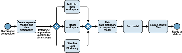
Componentization, or model referencing, in the BMS controller design allows you to develop the model and later integrate components into a single large model, thus enabling collaborative Model-Based Design development. Decide the appropriate location to store the data of the models based on your use case:
When experimenting with temporary models, store in the MATLAB base workspace.
When permanently storing data that is local to the model, store in the model workspace..
When permanently storing global data, sharing data between models, and tracking changes made to data, store in a Simulink data dictionary.
This activity diagram shows the ideal workflow for interface and data management.
Link to the model from the requirements provided. The data traceability file (.slmx file) contains the links associated with the model. Traceability between the development artifacts allows you to easily track defects and maintain files associated with the project. To help you manage data when building large composite model from scratch, as a best practice, you can describe the implementation at each level of the model.. For more information, see Graphically Manage Shared Interfaces, Data Types, and Constants.
Componentized data management supports:
Componentized development
Developing components or sub-components independently, without starting from the system model and without the rest of the system files being available
Easy data sharing without excessive linkage between components
Checking consistency of duplicate data definitions
Scoping data to the system and specific level of system hierarchy
Conclusion
This example provides guidance for systematic Model-Based Design development and highlights best practices and tools for collaborative design, including:
MATLAB and Simulink projects for file management
Requirements management with the Requirements Editor
System architecture and functionality
Model decomposition
Data management and data decomposition in a model
Getting started with unit-level, subsystem-level, and system-level workflows
Related Topics
- Basic Modeling Workflow
- Requirements Editor (Requirements Toolbox)
You can also select a web site from the following list:
Americas
- América Latina (Español)
- Canada (English)
- United States (English)
Europe
- Belgium (English)
- Denmark (English)
- Deutschland (Deutsch)
- España (Español)
- Finland (English)
- France (Français)
- Ireland (English)
- Italia (Italiano)
- Luxembourg (English)
- Netherlands (English)
- Norway (English)
- Österreich (Deutsch)
- Portugal (English)
- Sweden (English)
- Switzerland
- United Kingdom (English)